Real Terminal History.
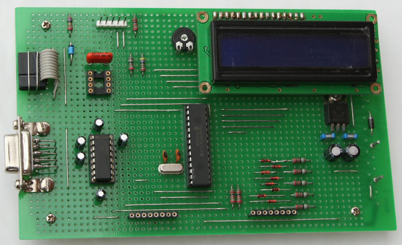
I have decided to make two prototypes. One called Real Terminal (RT), based on PIC16F873A, with a 2-line by 16 characters LCD display stuck on PORT-B of the MCU, a 4x4 hex keypad on PORT-A, together with an I2C interface on the same PORT, and use PORT-C as a communication port to the outer world, on which on a Time-Sharing basis I have implemented a RS-232 Serial protocol to a MAX232 and an SPI protocol in two ways. The first to an SPI connector for communicating directly with a similar board, and second to a ten-pin connector for communicating with Nordic’s nRF24L01 2.4GHz wireless transceiver.
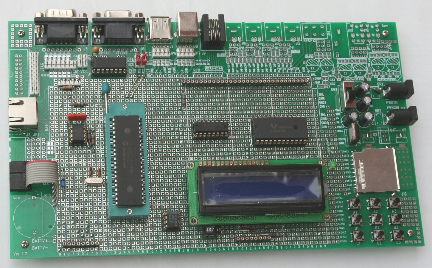
The second prototype, called Real Terminal Plus (RT+), following the same philosophy, was based on PIC16F877A, with the above ports used exactly the same way, plus PORT-D used to drive a vintage 12-digits fluorescent display via a CD4543 7-segment Display Driver and a CD4067 16-line Multiplexer down to 12-lines, both of them controlled by PORT-E of the MCU.
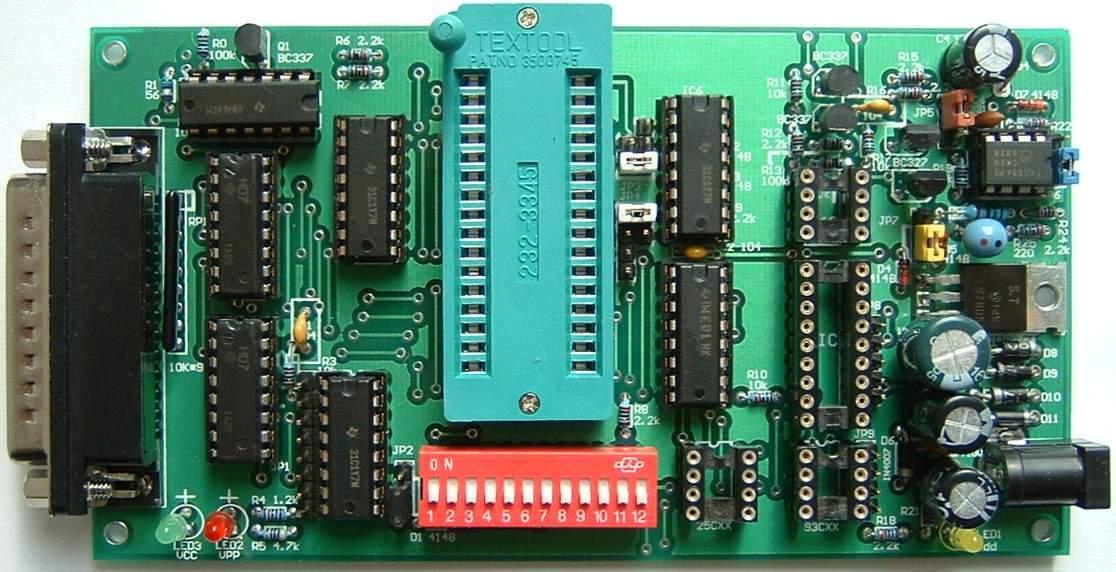
Both boards Microcontrollers capable of being programmed via an ICSP 5-pins connector, by my Willem Eprom Programmer vPCB 3.0 with 0.97ja software.
Extremely helpful proved to be Microchip’s MPLAB MPASM software implementation platform, who had created all the necessary .hex files, necessary to program the Microcontrollers with.
Throughout my experiments, I have decided to use RT as the Master board to establish communication with the Slave board (RT+) or my ACER Aspire Netbook via RealTerminal software.
First attempt was to read the keypad and display the keys pressed in a 16 by 2 LCD Display. This was accomplished by the following listings for the RT (873) and RT+ (877) respectivelly:
Real Terminal 873A.asm and
Real Terminal 877A.asm
Serial (RS-232) routines were embeded in the following listings:
Real Terminal 873A-serial.asm and
Real Terminal 877A-serial.asm
Next step was each board to communicate via the Serial Port of my Netbook in the conception of receiving data serially and sending them back to PC running RealTerminal software. Listings were respectivelly:
Real Terminal 873A-ser-test.asm and
Real Terminal 877A-ser-test.asm
It was rather easy then to use RT as a Master, reading the keypad and sending characters to the RT+ as Slave through serial port, displaying the characters on its LCD, using the listing below:
Real Terminal 873A-ser-test-send.asm
Now that I have succeeded with communication via RS-232 Serial, my attempts was to make the two boards communicate with each-other via the embeded in both Microcontrollers SPI protocol.
I have decided once more to use RT (873) as a Master device sending data to the Slave RT+(877). The RT reads the keypad and send the keys pressed to RT+ via SPI port. This time the listings were:
Real Terminal 873A-SPI-test-master.asm and
Real Terminal 877A-SPI-test-slave.asm
Some information useful for further reference concerning the SPI protocol is that plain SPI mode uses only three lines for MCUs to talk to each-other.
SDO which is the output, which sends data of the Master to Slave,
SDI which is the input, which receives data sent by the Slave to Master and
SCK which is the clock signal generated by the Master to control communication.
My thoughts now focus on testing NORDIC’s nRF24L01 2.4GHz wireless modules, using the SPI protocol mentioned above, to establish communication between RT and RT+. Essential here are three additional lines used by the RF module:
CE used to control the module,
CSN used to send SPI commands to the module and
IRQ used to send back to the MCU the Inerrupt signal (optional).
As a conclusion, I have used the following connections between the RT or RT+ and the nRF24L01 module:
VDD Plus (+) 3.2V stabilized from the RT or RT+ board,
CE Chip Enable from mainboards,
SCN Chip Select Not from mainboards,
SCK Serial Clock from mainboards,
MOSI SDO (output) from mainboards,
MISO SDI (input) to mainboards,
IRQ Interrupt to mainboards and
GND Ground from mainboards.
I am working now on the assembly code (as usual) trying to establish connection between the RT board and the RT+ board via the nRF24L01 module.
Last thought was to implement a third, portable board, called Real Terminal Mini (RT-) which will include a smaller LCD display (2-line by 8-characters) and probably SMD technique.
Athens, 31th of March, 2013
Stelios
SV1BKG